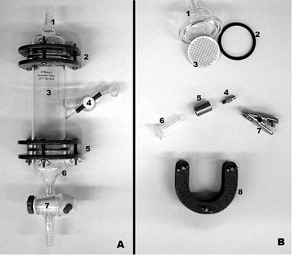
Figure 4. Flow-cell assembled and also showing some
components.
(a)
Assembled flow cell: 1) Top fitting for flow cell; 2) Upper horseshoe clamp for
holding top fitting with flow-cell body; 3) Flow-cell central body; 4) Adjustable
side-arm for the extraction of fluids and beads; 5) Lower horseshoe clamp for
holding bottom fitting; 7) Adjustable valve for regulating flow and extraction
of contents as well as allowing the upward flow of gasses such as N2 through the complete assembly.
(b) Expanded view of selected parts of flow-cell:
1) Top fitting for flow-cell; 2) O-ring between top fitting and main flow-cell
body; 3) Aluminium filter designed to contain alginate beads, but to allow for
liquid and gaseous flow; 4) Adapter fitting for Leur-Loc® syringe; 5) Glass-to-steel
intermediate adapter; 6) Fitting with ground-glass flanged surface to attach to
the side-arm of the central flow-cell body; 7) Clamp for holding the fitting
onto the side-arm; 8) View of horseshoe clamp with three tightening screws. |