
|
|
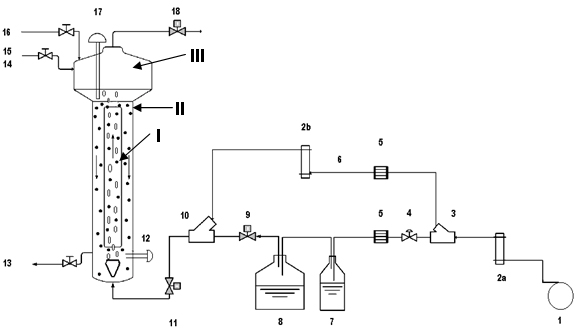
Figure 1. Schematic diagram of the experimental system used. Nomenclature: [1] air compressor; [2a, 2b] flow meters; [3] flow divider; [4] valve; [5] air filter; [6] dilution line; [7] condenser; [8] toluene saturator; [9] gas sample port; [10] mixer; [11] gas sample port; [12] pH electrode; [13] biomass drain; [14] NaOH supplement; [15]: re-circulation of support material; [16] nutrients; [17] thermal dome; [18] gas sample port. |
|
|